
")

Maglev Centrifugal Blower
Category:
Maglev Centrifugal Blower
The Maglev Centrifugal Blower is a mechanical device designed for conveying gases and powders. It incorporates core technologies such as magnetic levitation bearings, three-dimensional flow impellers, high-speed permanent magnet synchronous motors, efficient variable frequency speed regulation, and intelligent monitoring and control. Upon startup, the system first levitates and then rotates, operating without friction or the need for lubrication. The three-dimensional flow impeller is directly connected to the rotor, ensuring zero transmission loss. This makes it a high-tech, green, energy-saving, and environmentally friendly product.
The Maglev Centrifugal Blower utilizes non-contact, frictionless magnetic levitation bearings and a high-speed, high-power permanent magnet synchronous motor to directly drive the highly efficient fluid impeller. This design overcomes the drawbacks of traditional blowers, offering advantages such as high efficiency, low noise, minimal malfunctions, and the elimination of a lubrication system. Even in the event of a magnetic levitation bearing failure, the system's protective bearings ensure the safe deceleration of the high-speed rotor, preventing severe damage to the equipment.
Maglev Centrifugal Blower vs. Traditional Blower
| Fan Type | Roots Blower | Single-Stage Blower | Multi-Stage Blower | Magnetic Levitation Blower |
| Bearing Type | Ball Bearing | Ball Bearing | Ball Bearing | Magnetic Bearing |
| Bearing Lubrication | Required | Required | Required | Not Required |
| Bearing Lifespan | 1-2 Years | 3-5 Years | 2-3 Years | Semi-Permanent |
| Bearing Energy Consumption | 2-5% | 2-5% | 2-5% | 1% |
| Impeller Type | Cast Two or Three Lobes | Aluminum Alloy Three-Dimensional Flow Impeller | Welded Carbon Steel or Cast Aluminum | Aluminum Alloy or Titanium Alloy Three-Dimensional Flow Impeller |
| Impeller Efficiency | Low | Relatively High | Low | High |
| Motor Type | Low-Speed Asynchronous Motor | Asynchronous AC Motor | Low-Speed Asynchronous Motor | High-Speed Permanent Magnet Motor |
| Motor Transmission Mode | Belt/Coupling | Coupling | Coupling | Direct Drive |
| Motor Efficiency | 85-90% | 85-90% | 85-90% | Above 95% |
| Motor Cooling | Air-Cooled | Air-Cooled | Water-Cooled | Air-Cooled/Water-Cooled |
| Motor Speed Control | Non-Adjustable | Non-Adjustable | Non-Adjustable | Precise Control |
| Noise Level | Above 100 dB | 90-100 dB | Around 100 dB | Around 80 dB |
| Vibration Level | High | Relatively High | Relatively High | Minimal |
| Maintenance Cost | Bearings, Gears, Lubricant | Bearings, Gears, Lubricant Pump | Bearings, Seals, Lubricant | Filter Screen |
| Installation | Hoisting, Ground Fixing | Hoisting, Ground Fixing | Hoisting, Ground Fixing | Forklift, Ground Leveling |
| Size | Large | Large | Large | Small |
| Overall Efficiency | Low | Relatively Low | Low | High |
| Operating Cost | Highest | Medium | High | Very Low |
| Procurement Cost | Lowest | High | Medium | High |
Magnetic Levitation Motor Assembly
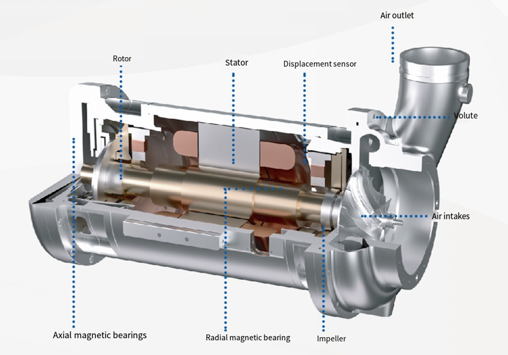
The high-speed centrifugal impeller is designed based on the three-dimensional flow theory with optimized parameters, which maximizes the impeller efficiency and broadens its operating range. Made of high-strength forged aluminum or titanium alloy, it has strong resistance to deformation. It is precisely machined by a CNC machining center, and the surface of the impeller undergoes anodizing treatment to enhance its corrosion resistance and wear resistance.
Driven by a motor, the impeller rotates. The blades in the impeller force the gas to rotate, doing work on the gas and increasing its energy. Under the action of centrifugal force, the gas is flung to the periphery of the impeller. The volute casing then converts the kinetic energy of the gas into pressure energy. When the gas in the impeller is discharged, the pressure inside the impeller is lower than that at the inlet. New gas is drawn into the impeller under the action of the pressure difference, and the gas is continuously output from the outlet.
Permanent magnets are installed on the motor shaft to ensure its magnetism. The coils wound around the stator silicon steel sheets of the motor generate magnetic force. During operation, the speed and the magnetic field remain consistent to achieve synchronization. The permanent magnet motor uses magnetic levitation bearings, featuring no mechanical friction, low noise, low vibration, and long service life. Its maximum rotational speed can reach 70,000 r/min.
It focuses on high frequency, with a carrier frequency as high as 16 kHz and an output frequency up to 800 Hz. It can easily drive high-speed motors, with excellent loss suppression and heat management. High-frequency output does not reduce capacity and is suitable for various harsh operating environments. The high-performance sensorless vector control technology has good parameter adaptability, high control performance, low output harmonics, and low motor heating. With intelligent self-learning, it can identify motor parameters and control parameters with one click, significantly reducing debugging difficulty and workload.
Model selection and parameters
| Model | KFM37 | KFM55 | KFM75 | KFM90 | KFM110 | KFM132 | KFM150 | KFM200 | KFM250 | KFM300 | KFM350 |
| Motor power/kW | 37 | 55 | 75 | 90 | 110 | 132 | 150 | 200 | 250 | 300 | 350 |
| Outlet pressure/kPa | Flow rate (m³/min) | ||||||||||
| 40 | 41 | 68 | 87 | 100 | 115 | 146 | 177 | 221 | 277 | 332 | 465 |
| 50 | 38 | 58 | 77 | 91 | 107 | 134 | 162 | 202 | 253 | 304 | 385 |
| 60 | 34 | 49 | 69 | 82 | 99 | 121 | 146 | 183 | 228 | 274 | 325 |
| 70 | 30 | 45 | 62 | 74 | 91 | 108 | 131 | 164 | 205 | 246 | 285 |
| 80 | 27.5 | 41 | 54 | 67 | 84 | 98 | 119 | 149 | 186 | 223 | 255 |
| 90 | 25 | 37 | 50 | 61 | 74 | 90 | 108 | 136 | 170 | 204 | 218 |
| 100 | - | - | - | 51 | 63 | 80 | 96 | 120 | 152 | 170 | 195 |
| 120 | - | - | - | 45 | 55 | 68 | 80 | 100 | 125 | 140 | 180 |
| Cooling metdod | Air cooling (for tde first 8 models) | Air cooling + water cooling (for tde last 3 models) | |||||||||
| Driving metdod | Integral direct drive for all models | ||||||||||
| Outlet pipe diameter/DN | 200 (for tde first 3 models) | 250 (for tde next 2 models) | 300 (for tde next 2 models) | 400 (for tde last 4 models) | |||||||
Note: KFM110 (K - Kaifeng, F - Float, M - Magnetic Levitation, 110 - Power)
Performance curve diagram
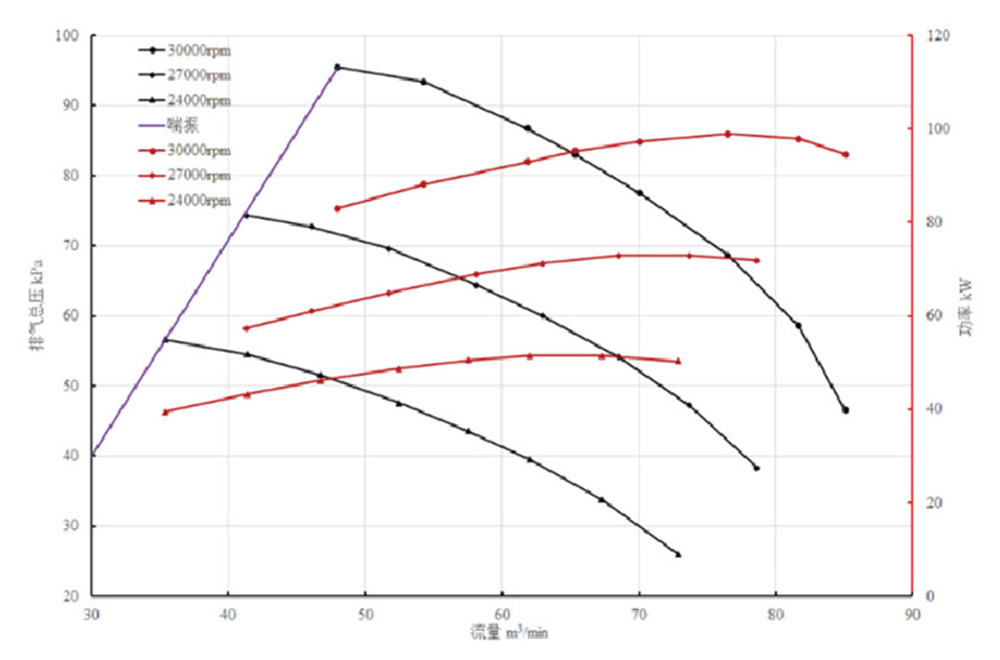
Note: Black vertical axis: Exhaust pressure kPa; Horizontal axis: Flow rate m³/min; Red vertical axis: Power kW
Previous
Next
Previous
Maglev Vacuum Pump
Next


Address: Building C, Pengyao Environmental Protection Technology Innovation Park, No. 25 Saite Avenue, Yixing City, Jiangsu Province
Contact: Mr.Chen
E-mail: j.chen@kaifengtech.com

WeChat official account
Copyright © 2025 Yixing Kaifeng Technology Co., Ltd | SEO
Power by: www.300.cn


